Table of Contents
What is manometer
The term manometer comes from the Greek words’manós’, which means thin or rare, and’métron,’ which means measure. A manometer is a device that measures the pressure (static pressure) exerted by a still liquid or gas based on the idea of hydrostatic equilibrium. The pressure at any location in a fluid at rest is equal, and its value is equal to the weight of the overlying fluid, according to hydrostatic equilibrium. The manometer is the most basic instrument for measuring gauge pressure (low-range pressure) by balancing pressure against the weight of a liquid column. All manometers work by measuring the influence of pressure exerted by a fluid at a depth. Following are the advantages of manometers:
- Simple and time-proven.
- They have high accuracy and sensitivity.
- Availability of a wide range of filling fluids of varying specific gravities.
- It has a reasonable cost.
- There are suitable for low pressure and low differential pressure applications.
Types of manometers
Simple U-tube Manometer
A manometer is a pressure measuring instrument. A simple manometer is made out of a U-shaped glass tube filled with liquid. This sort of manometer is made up of an incompressible fluid, such as water or mercury, in its most basic form. Because of its high density, mercury is usually the culprit.
Consider a U-shaped tube whose both ends are open to the atmosphere is filled with a liquid. The points A and B, Fig.1.1 (a), are at atmospheric pressure and at the same perpendicular height. In another case, Fig.1.1 (b), consider that the left arm of the U-tube top end is closed and there’s a sample of gas in the unrestricted end of the tube. The right side of the tube remains open to the atmosphere. Point A, also, is at atmospheric pressure. Point C is at the pressure of the gas in the unrestricted end of the tube. Point B has a pressure lesser than atmospheric pressure due to the weight of the column of liquid of height h. Point C is at the same height as B, so it has the same pressure as point B. Therefore, pressure at point C is equal to the pressure of the gas in the unrestricted end of the tube. The pressure of the gas trapped in the unrestricted end of the tube is lesser than the atmospheric pressure by the quantum of pressure wielded by the column of liquid of height.
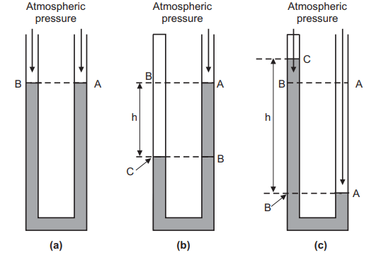
Another possible arrangement of the manometer is where the top of the left side of the tube is closed and the unrestricted end of the tube contains a sample of gas or it contains a vacuum, Fig.1.1 (c). Point A is at atmospheric pressure. Point C is at some pressure if it contains gas in the unrestricted end of the tube. Since point B is at the same height as point A, it’s at atmospheric pressure. But the pressure at point B is also the sum of the pressure at point C and the pressure wielded by the weight of the column of liquid of height h in the tube. Therefore, it can be concluded that pressure at point C is lower than atmospheric pressure by the quantum of pressure wielded by the column of liquid of height. However, also the pressure at point C is zero, and atmospheric pressure is equal to the pressure wielded by the weight of the column of liquid of height h If the unrestricted end of the tube contains a vacuum. The U-tube manometer is affordable and doesn’t need estimation.
Pressure is defined as the force per area. The SI unit for pressure is the pascal, which is N/m2. Another common unit for measuring atmospheric pressure is mm of mercury, whose value is usually about 760 mm. If the closed end of the tube, Fig. 1.1(c), contains a vacuum, the height h is about 760 mm. In many situations, measuring pressures in units of length of the liquid in the manometer is perfectly adequate.
The pressure measurement in the manometer is calculated by considering a cylinder of liquid of height h and area A. The weight of the cylinder is its mass ‘m’ times the acceleration due to gravity ‘g’. This is the force exerted by the cylinder of liquid on whatever is just below it. It is expressed as :
F = m g …. (1.3)
The pressure ‘P’ is this force divided by the area ‘A’ of the face of the cylinder and is expressed as :
P = F A …. (1.4)
The mass of the cylinder is the density of the liquid ‘ρ’ times the volume ‘V’. m = ρ × V …. (1.5)
The volume is the area ‘A’ of the face of the cylinder times its height ‘h’. V = A × h …. (1.6)
So, the pressure P is: P = F/A
P = (m × g) /A
Since, m = ρ × V;
P = (ρ × V × g) /A
P = (ρ × A × h × g)/ A
P = ρ × h × g … (1.7)
Differential U-tube Manometer
A discriminational manometer is a device that measures the difference in pressure between two places. They can range from simple to complex digital outfits. Standard manometers are used to measure the pressure in a vessel by comparing it to normal atmospheric pressure. Differential manometers are also used to compare the pressure of two different holders. They’re used to knowing which vessel has lesser pressure and how large the difference between the two is.
The simplest discriminations manometer is a U-shaped tube with both ends at the same height. A liquid generally used is water or mercury and it rests at the bottom of the tube. However, the pressure will push down the liquid on that side of the tube, If one end of the tube is in a place with advanced air pressure. By measuring the difference between the heights of liquid, it’s possible to calculate the difference in pressure. To calculate the difference in pressure, the difference in height is multiplied by the viscosity of the gas and the acceleration due to graveness.
There are two types of differential manometer namely;
(i) U-tube differential manometer.
(ii) Inverted U-tube differential manometer.
There are two types of U-tube differential manometers.
(a) U-tube differential manometer at the same level.
(b) U-tube differential manometer at different levels.
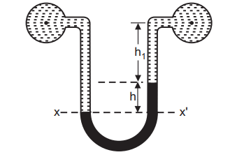
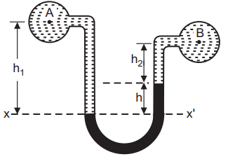
The first type of manometer has two pipes in a resemblant position, Figure1.2. This type of manometer is used for measuring the fluid pressure difference between these two pipes arranged at the same position. The alternate type of manometer, Fig.1.3, is used where two pipes are at different places and aren’t in resemblant condition. This type of manometer is used for measuring the fluid pressure between these two pipes arranged in different situations. Differential manometers have a wide range of uses in different disciplines. One illustration is that they can be used to measure the inflow dynamics of gas by comparing the pressure at different points in the pipe.
Inverted U-tube Manometer
The reciprocal of the U-tube differential manometer at a different level is the inverted U-tube differential manometer. When the pressure is increased, this sort of manometer is used to measure the precision of minor differences. For detecting pressure differences in liquids, an inverted U-tube manometer (Fig. 1.4) is utilized. The manometer’s space above the liquid is filled with air. A tap at the top allows you to regulate the liquid level in the manometer by admitting or expelling air. In a continuous body of static fluid, the pressure at the same level is equal.
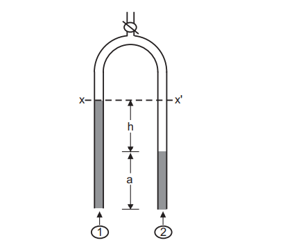
The pressure at level XX’ is equated as follows: For the left arm of the manometer:
Px = P1 − ρ g (h + a) … (1.8)
where Px is pressure in the left arm at point X, P1 is pressure in the left arm fluid, ρ is the density of
the air and g is the gravitational force. For the right arm of the manometer:
Px’= P2 − (ρ g a + ρm g h) …. (1.9)
where ρm is the density of mercury. Since, Px = Px’ …. (1.10)
P1 – ρ g (h + a) = P2 − (ρ g a + ρm g h)
P1 − P2 = (ρ − ρm) g h …. (1.11)
If the manometric fluid is chosen in such a way that ρm << ρ then,
P1 − P2 = ρ g h …. (1.12)
For an inverted U-tube manometer, the manometric fluid is usually air.
Micro Manometer
A micromanometer is used to measure extremely small pressure variations accurately. The micromanometer is a liquid column manometer that works on the same concept as the inclined tube manometer. The inclined tube’s meniscus is at a reference level, as shown in Fig. 1.5 when viewed through a magnifier with a cross hairline. P1 = P2 is the condition for which this is done. The well is adjusted by pushing it up and down a micrometer. When P1 P2, the change in the meniscus position is restored to zero by raising or lowering the well as previously, and the difference between these two readings is used to calculate the pressure difference in terms of height.
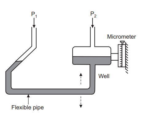
Micromanometer is a static fluid pressure difference measuring device. Its dynamics can rarely be ignored. Considering manometric fluid as a free body, the forces acting on it are
(i) The weight is distributed over the entire fluid.
(ii) The drag force due to its motion and the corresponding tube wall shearing stress.
(iii) The force due to differential pressure.
(iv) Surface tension force at the two ends.
Inclined Manometer
The ratio of mercury density (m) to the density of water (w) must be near to unity for accurate measurement of minor pressure variations by a standard U-tube manometer. If the working fluid is a gas, this is not possible. It is not always possible to create a manometric liquid with a density comparable to that of the working liquid while maintaining a well-defined meniscus at the interface. An inclined tube manometer is used for this purpose.
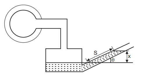
If the transparent tube of a manometer, instead of being vertical, is set at an angle ‘θ’ to the horizontal, Fig. 1.6, then a pressure difference corresponding to a vertical difference of levels ‘x’ gives a movement of the meniscus
s =x/sin θ
along the slope. If ‘θ’ is small, a considerable magnification of the movement of the meniscus may be achieved. Angles less than 50° are not usually satisfactory, because it becomes difficult to determine the exact position of the meniscus. One arm of this manometer is usually made large in cross-section than the other.