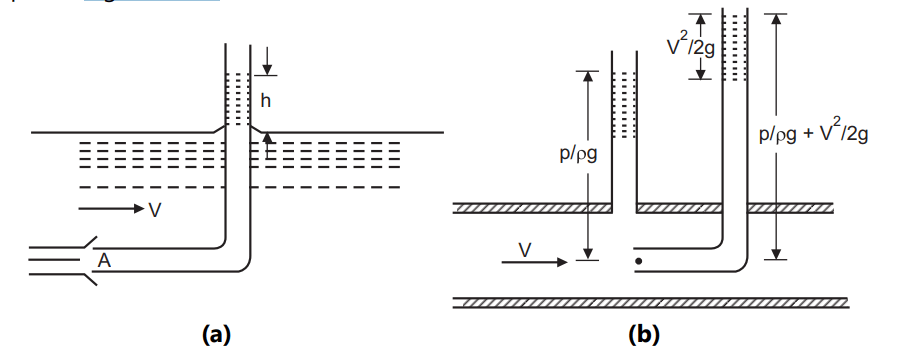
The pitot tube is a fluid flow measurement instrument designed by Henri Pitot, a French engineer in the 18th century. The Pitot tube principle of flow measurement was initially used to measure the velocity of water in a river. For this, a right-angled big glass tube was employed. The tube has one end that confronts the fluid flow and the other that is open to the atmosphere, Fig. 1.16 (a).
(b) Static and Stagnation Tubes Together
Table of Contents
Working of Pitot tube
A pitot tube is a simple round cylinder with a tiny hole at one end and an enclosed end. The fluid in the pipe flows into the Pitot tube and settles there. Another chamber within the Pitot tube is filled with static-pressure fluid. A diaphragm separates both chambers. The differential pressure is calculated by subtracting the dynamic pressure from both pressures. Dynamic pressure is measured by the difference in level between the liquid in the tube and the free surface. The square root of the pressure is used to compute the flow rate. The flow rate is determined by the tube design and the static tap’s position. The Pitot-static probe incorporates the static holes in the tube system to eliminate this parameter.
The liquid flows up the tube, reaching a height above the free surface of the water stream when equilibrium is reached. The measurement of static and impact pressures is accomplished with the use of an appropriate differential pressure metre, which determines flow velocity and hence the flow rate. The difference in level between the liquid in the glass tube and the free surface becomes the measure of dynamic pressure because the static pressure is equal to the hydrostatic pressure due to its depth below the free surface. As a result, ignoring friction, we can write,
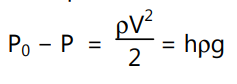
Equation … (1.52)
where, P0, P and V are the stagnation pressure, static pressure, and velocity respectively at point A, Fig. 1.16 (a).
This single tube is adequate to calculate the velocity of an open stream of liquid with a free surface. The Pitot tube, however, only detects the stagnation pressure for a fluid running through a closed duct, therefore the static pressure must be measured independently. In this situation, static pressure is measured at the wall’s edge, as shown in Fig. 1.16. (b). The axis of the tube measuring static pressure must be perpendicular to the border and free of burrs, resulting in a clean boundary and straight streamlines adjacent to it. This is done in order to detect only the static pressure and not any of the dynamic pressure. The piezometric tube, which measures static pressure, and the end of the Pitot tube, which measures stagnation pressure, can be coupled to an appropriate differential manometer to determine flow velocity and thus flow rate.
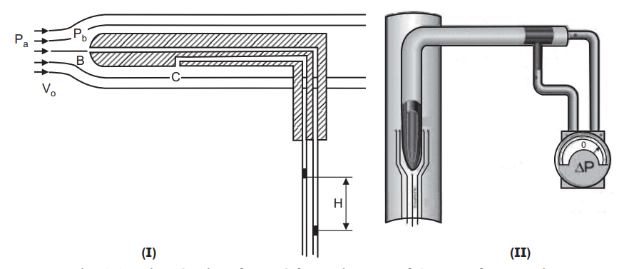
The static and stagnation pressure tubes are merged into a single instrument known as the Pitot static tube (Fig. 1.17). The static tube, which surrounds the Pitot tube that monitors the stagnation pressure, is used to detect static pressure. Two or more holes are bored radially into annular space through the outer wall of the static tube. The placement of these static holes is crucial. The flow is somewhat accelerated downstream of the tube’s snout, resulting in a reduction in static pressure. However, there is a decrease in velocity and an increase in pressure in front of the supporting stem.. The static holes should therefore be at the position where the two opposing effects are counterbalanced and the reading corresponds to the undisturbed static pressure.
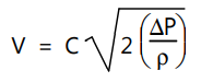
The flow velocity is given by
Equation… (1.53)
where ∆p is the difference between stagnation and static pressures. Factor C takes care of the non-idealities, due to friction, in converting the dynamic head into pressure head and depends, to a large extent, on the geometry of the Pitot tube. The value of C is usually determined from the calibration test of the Pitot tube.
Applications:
- It is widely used to measure the airspeed of aircrafts, speedboat speed and for fluid flow measurement in industrial application.
- Pitot tubes are mainly used for gas lines.
- These may be employed where the flowing fluid is not enclosed in a pipe or duct. For
- example, for measuring the flow of river water, or for measuring air flow in aeroplane.
Advantages:
- Pitot tube is small and do not contain any moving parts.
- Low permanent pressure loss.
- Loss of head is negligible by insertion of Pitot tube.
- It is very cheap as compared to venturi meter, orifice plate and flow nozzle.
- Ease of installation into an existing system.
Disadvantages:
- The differential pressures produced are usually low, say of the order of 250 Pa, and so their sensitivity is low.
- Pitot tube requires higher flow velocity in order to produce measurable heads.
- It has small openings which get clogged due to passing solid particles and thus may disrupt normal reading as a result.
- It requires high fluid velocity, of the order 15 m/s to produce a measurable differential pressure.
- There is no standardization of pitot tubes. Each Pitot tube is required to be calibrated for each installation.
Make sure check our amazing article: Working construction of Venturi Meter