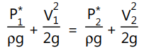
The orifice meter is made-up of chrome steel, phosphor bronze, nickel, and monel. An orifice meter provides an easier and cheaper arrangement for the measurement of flow through a pipe. An orifice is a thin circular plate with a sharp-edged concentric circular hole in it. The main part of an orifice flow meter may be a chrome steel orifice plate which is held between flanges of a pipe carrying the fluid whose flow is being measured. An orifice plate is fitted between the flanges which are at a certain distance. In order to maintain laminar flow conditions, the pipe carrying the fluid is straight. Openings are provided at two places (a) and (b) for attaching a differential pressure sensor (U-tube manometer, a differential pressure gauge) as shown in Fig. 1.13. The area (A0) of the orifice is far smaller than the cross-sectional area of the pipe. The flow from an upstream is uniform and adjusts itself in such a manner that it contracts until a section downstream the orifice plate is reached at vena contracta (b) and then expands to fill the passage of the pipe. The vena-contracta length depends on the roughness of the inner wall of the pipe and therefore the sharpness of the orifice plate. One of the pressure tapings is provided at a distance equal to the diameter of the pipe upstream of the orifice plate where the flow is almost uniform (a) and the other at a distance of half a diameter of the pipe downstream of the orifice plate.
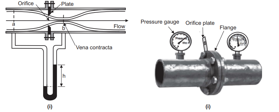
Table of Contents
Operation:
In order to understand how the orifice meter works the small print of the fluid movement inside the pipe and orifice plate has got to be understood. The fluid having a uniform cross-section of flow converges into the orifice plate’s opening in its upstream (left side). When the fluid comes out of the orifice plate’s opening, its cross-section is minimum and uniform for a specific distance then the cross-section of the fluid starts diverging downstream (right side). At the upstream of the orifice, before the converging of the fluid, the pressure of the fluid (P1) is at maximum. As the fluid starts converging and enters the orifice opening its pressure drops. Whereas, when the fluid comes out of the orifice opening, its pressure is minimum (P2) and this minimum pressure remains constant in the minimum cross-sectional area of fluid flow downstream. This minimum cross-sectional area of the fluid obtained downstream from the orifice edge is named vena-contracta. The manometer attached between points (a) and (b) records the pressure difference (∆P = P1 – P2) between these two points which becomes an indication of the flow rate of the fluid through the pipe when calibrated.
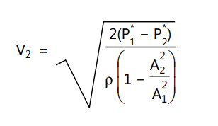
Considering the fluid to be ideal and the downstream pressure taping to be at the vena contracta, we can write, by applying Bernoulli’s theorem between (a) and (b) as
… (1.32)
where, P*1 and P*2 are the piezometric pressures at (a) and (b), respectively. From the equation of continuity,
V1 A1 = V2 A2 …. (1.33)
where A2 is the area of the vena contracta. With the help of equation (1.32), equation (1.33) can be written as
… (1.34)
Applications of Orifice Meter
- The concentric orifice plate is used to measure flow rates of pure fluids.
- The eccentric and segmental orifice plates are used to measure flow rates of fluids containing suspended materials such as solids, oil mixed with water and wet steam.
Advantages of Orifice Meter
- It is a very cheap and easy method.
- It has predictable characteristics and requires less space.
- It can be used to measure flow rates in large pipes.
Limitations of Orifice Meter
- In certain cases it becomes difficult to tap the minimum pressure (P2) due to the roughness of the inner wall of the pipe and the sharpness of the orifice plate.
- Pressure recovery downstream is poor, i.e. overall loss varies from 40% to 90% of the differential pressure.
- The upstream pipe must be straight to obtain laminar flow.
- Chances of clogging the orifice when the suspended fluid flows.
- The orifice plate gets corroded and due to this, there may be inaccuracy in determination.
- The orifice plate has low physical strength.
- The coefficient of discharge is low.