The shell and tube heat exchanger are the most commonly used heat exchangers in the chemical process industries. This type of heat exchanger consists of a bundle of tubes properly secured at the ends in tube sheets. The metal sheets have holes into which the tubes are fixed up to have leak-proof joints. The entire tube bundle is placed inside a closed shell in such a way that it forms two immiscible zones for hot and cold fluids. One fluid flows through the tubes whereas the other fluid flows around the outside of the tubes within the space between the tube sheets and is enclosed by the outer shell. The proper fluid distribution of the shell side fluid is achieved by placing baffles normal to the tube bundle. Baffle creates turbulence in the shell side fluid and enhances the transfer coefficients for the shell side flow.
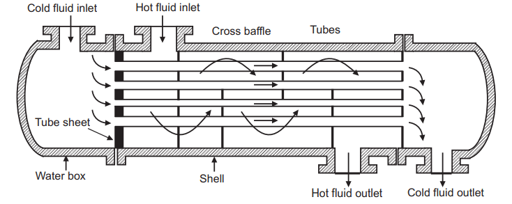
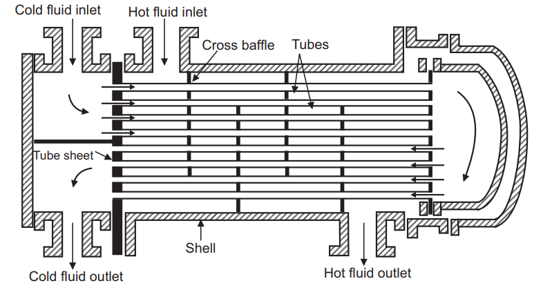
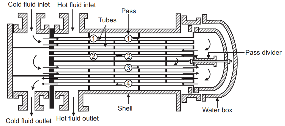
The tube heat exchanger, Fig. 4.5, have one shell and one tube pass since both the shell and tube side fluid make a single traverse through the heat exchanger. Thus, this type of heat exchangers is designated as 1-1 exchanger. If the tube fluid passes twice it is designated as 1-2 exchangers. Similarly, if heat exchanger has 2 shell pass and 4 tube pass, it is designated as 2-4 exchangers. The number of pass in the tube side is done by the pass partition plate. A pass partition plate is shown in Fig. 4.6. The shell side pass can be created by a flat plate as shown in Fig. 4.7.
In reality, this type of shell and tube heat exchanger is used in the process industry and is quite complex and is improved in design for thermal expansion stresses, tube fouling due to contaminated fluids, ease of assembling, and disassembling, size, weight, etc. The area available for the flow of the tube side fluid is inversely proportional to the number of passes. Thus, on increasing the number of passes the area reduces, and as a result, the velocity of the fluid in the tube increases, and henceforth the Reynolds number also increases. It results in an increased heat transfer coefficient but it is at the cost of a high-pressure drop. Generally, even numbers of tube passes are preferred for the multi-pass heat exchangers.
The commonly used method of classifying heat exchangers is indirect contact type or direct contact type heat exchangers.
(A) Indirect contact type heat exchangers:
In many heat exchangers, the fluids are separated by a heat transfer surface, and ideally, they do not mix or leak. Such
exchangers are referred to as direct transfer types.
(i) Direct transfer type
(ii) Storage type
(iii) Fluidized bed type
(B) Direct contact type:
Exchangers in which there is intermittent heat exchange between the hot and cold fluids via thermal energy storage and release through the exchanger surface are referred to as indirect transfer types.
(i) Immiscible fluids
(ii) Gas-liquid
(iii) Liquid-vapour
Make sure check our amazing article on: What is heat transfer?